21. Distributed Systems
The rest of the course is about distributed computing systems. In the next four lectures we will characterize distributed systems and study how to specify and implement communication among the components of a distributed system. Later lectures consider higher-level system issues: distributed transactions, replication, security, management, and caching.
The lectures on communication are organized bottom-up. Here is the plan:
1. Overview.
2. Links. Broadcast networks.
3. Switching networks.
4. Reliable messages.
5. Remote procedure call and network objects.
Overview
An underlying theme in computer systems as a whole, and especially in distributed systems, is the tradeoff between performance and complexity. Consider the problem of carrying railroad traffic across a mountain range.[1] The minimal system involves a single track through the mountains. This solves the problem, and no smaller system can do so. Furthermore, trains can travel from East to West at the full bandwidth of the track. But there is one major drawback: if it takes 10 hours for a train to traverse the single track, then it takes 10 hours to switch from E-W traffic to W-E traffic, and during this 10 hours the track is idle. The scheme for switching can be quite simple: the last E?W train tells the W-E train that it can go. There is a costly failure mode: the East end forgets that it sent a ‘last’ E-W train and sends another one; the result is either a collision or a lot of backing up.
The simplest way to solve both problems is to put in a second track. Now traffic can flow at full bandwidth in both directions, and the two-track system is even simpler than the single-track system, since we can dedicate one track to each direction and don’t have to keep track of which way traffic is now running. However, the second track is quite expensive. If it has to be retrofitted, it may be as expensive as the first one. A much cheaper solution is to add sidings: short sections of double track, at which trains can pass each other. But now the signaling system must be much more complex to ensure that traffic between sidings flows in only one direction at a time, and that no siding fills up with trains.
What makes a system distributed?
One man’s constant is another man’s variable.
Alan Perlis
A distributed system is a system where I can’t get my work done because a computer has failed that I’ve never even heard of.
Leslie Lamport
There is no universally accepted definition of a distributed system. It’s like pornography: you recognize one when you see it. And like everything in computing, it’s in the eye of the beholder. In the current primitive state of the art, Lamport’s definition has a lot of truth.
Nonetheless, there are some telltale signs that help us to recognize a distributed system:
It has concurrency, usually because there are multiple general-purpose computing elements. Distributed systems are closely related to multiprocessors.
Communication costs are an important part of the total cost of solving a problem on the system, and hence you try to minimize them. This is not the same as saying that the cost of communication is an important part of the system cost. In fact, it is more nearly the opposite: a system in which communication is good enough that the programmer doesn’t have to worry about it (perhaps because the system builder spent a lot of money on communication) is less like a distributed system. Distributed systems are closely related to telephone systems; indeed, the telephone system is by far the largest example of a distributed system, though its functionality is much simpler than that of most systems in which computers play a more prominent role.
It tolerates partial failures. If some parts break, the rest of the system keeps doing useful work. We usually don’t think of a system as distributed if every failure causes the entire system to go down.
It is scaleable: you can add more components to increase capacity without making any qualitative changes in the system or its clients.
It is heterogeneous. This means that you can add components that implement the system’s internal interfaces in different ways: different telephone switches, different computers sending and receiving E-mail, different NFS clients and servers, or whatever. It also means that components may be autonomous, that is, owned by different organizations and managed according to different policies. It doesn’t mean that you can add arbitrary components with arbitrary interfaces, because then what you have is chaos, not a system. Hence the useful reminder: “There’s no such thing as a heterogeneous system.”
Layers
Any idea in computing is made better by being made recursive.
Brian Randell
There are three rules for writing a novel.
Unfortunately, no one knows what they are.
Somerset Maugham
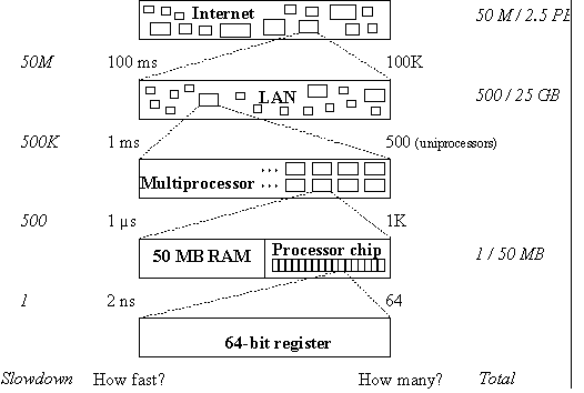
You can look at a computer system at many different scales. At each scale you see the same basic components: computing, storage, and communications. The bigger system is made up of smaller ones. Figure 1 illustrates this idea over about 10 orders of magnitude (we have seen it before, in the handout on performance.
|
Fig. 1. Scales of interconnection. Relative speed and size are in italics. |
But Figure 1 is misleading, because it doesn’t suggest that different levels of the system may have quite different interfaces. When this happens, we call the level a layer. Here is an example of different interfaces that transport bits or messages from a sender to a receiver. Each layer is motivated by different functionality or performance than the one below it. This stack is ten layers deep. Note that in most cases the motivation for separate layers is either compatibility or the fact that a layer has other clients or other implementations.
|
|
What |
Why |
|
a) |
a TCP reliable transport link |
function: reliable stream |
|
b) |
on an Internet packet link |
function: routing |
|
c) |
on the PPP header compression protocol |
performance: space |
|
d) |
on the HDLC data link protocol |
function: packet framing |
|
e) |
on a 14.4 Kbit/sec modem line |
function: byte stream |
|
f) |
on an analog voice-grade telephone line |
function: 3 KHz low-latency signal |
|
g) |
on a 64 Kbit/sec digital line multiplexed |
function: bit stream |
|
h) |
on a T1 line multiplexed |
performance: aggregation |
|
i) |
on a T3 line multiplexed |
performance: aggregation |
|
j) |
on an OC-48 fiber. |
performance: aggregation |
On top of TCP we can add four more layers, some of which have interfaces that are significantly different from simple transport.
|
|
What |
Why |
|
w) |
mail folders |
function: organization |
|
x) |
on a mail spooler |
function: storage |
|
y) |
on SMTP mail transport |
function: routing |
|
z) |
on FTP file transport |
function: reliable char arrays |
Now we have 14 layers with two kinds of routing, two kinds of reliable transport, three kinds of stream, and three kinds of aggregation. Each serves some purpose that isn’t served by other, similar layers. Of course many other structures could underlie the filing of mail messages in folders.
Here is an entirely different example, an implementation of a machine’s load instruction:
|
|
What |
Why |
|
a) |
load from cache |
function: data access |
|
b) |
miss to second level cache |
performance: space |
|
c) |
miss to RAM |
performance: space |
|
d) |
page fault to disk |
performance: space |
Layer (d) could be replaced by a page fault to other machines on a LAN that are sharing the memory (function: sharing)[2], or layer (c) by access to a distributed cache over a multiprocessor’s network (function: sharing). Layer (b) could be replaced by access to a PCI I/O bus (function: device access), which at layer (c) is bridged to an ISA bus (function: compatibility).
Another simple example is the layering of the various facsimile standards for transmitting images over the standard telephone voice channel and signaling. Recently, the same image encoding, though not of course the same analog encoding of the bits, has been layered on the internet or e-mail transmission protocols.
Addressing
Another way to classify communication systems is in terms of the kind of interface they provide:
messages or storage,
the form of addresses,
the kind of data transported,
other properties of the transport.
Here are a number of examples to bear in mind as we study communication. The first table is for messaging, the second for storage.
|
System |
Address |
Sample address |
Data value |
Delivery |
|
|
|
|
|
|
|
Ordered |
Reliable |
|
|
J-machine[3] |
source route |
4 north, 2 east |
32 bytes |
yes |
yes |
|
|
IEEE 802 LAN |
6 byte flat |
FF F3 6E 23 A1 92 |
packet |
no |
no |
|
|
IP |
4 byte hierarchical |
16.12.3.134 |
packet |
no |
no |
|
|
TCP |
IP + port |
16.12.3.134 / 3451 |
byte stream |
yes |
yes |
|
|
RPC |
TCP + procedure |
16.12.3.134 / 3451 / Open |
arg. record |
yes |
yes |
|
|
|
host name + user |
String |
no |
yes |
||
|
System |
Address |
Sample address |
Data value |
|
|
Main memory |
32-bit flat |
04E72A39 |
2n bytes, n?4 |
|
|
File system[4] |
path name |
/udir/bwl/Mail/inbox/214 |
0-4 Gbytes |
|
|
World Wide Web |
protocol + |
http://research.microsoft.com/ |
typed, |
|
Layers in a communication system
The standard picture for a communication system is the OSI reference model, which shows peer-to-peer communication at each of seven layers (given here in the opposite order to the examples above):
physical (volts and photons),
data link,
network,
transport,
session,
presentation, and
application.
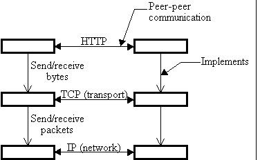
This model is often, and somewhat pejoratively, called the ‘seven-layer cake’. The peer-to-peer aspect of the osi model is not as useful as you might think, because peer-to-peer communication means that you are writing a concurrent program, something to be avoided if at all possible. At any layer peer-to-peer communication is usually replaced with client-server communication (also known as request-response or remote procedure call) as soon as possible.
|
Fig. 2: Protocol stacks for peer-to-peer communication |
The examples we have seen should make it clear that real systems cannot be analyzed so neatly. Still, it is convenient to use the first few layers as tags for important ideas, which we will study in this order:
Data link layer: framing and multiplexing.
Network layer: addressing and routing (or switching) of packets.
Transport layer: reliable messages.
Session layer: naming and encoding of network objects.
We are not concerned with volts and photons, and the presentation and application layers are very poorly defined. Presentation is supposed to deal with how things look on the screen, but it’s unclear, for example, which of the following it includes: the X display protocol, the Macintosh pict format and the PostScript language for representing graphical objects, or the Microsoft rtf format for editable documents. In any event, all of these topics are beyond the scope of this course.
Figure 2 illustrates the structure of communication and implementation for a fragment of the Internet.
Principles
There are a few important ideas that show up again and again at the different levels of distributed systems: recursion, addresses, end-to-end reliability, broadcast vs. point-to-point, real time, and fault-tolerance.
Recursion
The 14-layer example of implementing E-mail gives many examples of encapsulating a message and transmitting it over a lower-level channel. It also shows that it is reasonable to implement a channel using the same kind of channel several levels lower.
Another name for encapsulation is ‘multiplexing’.
Addresses
Multi-party communication requires addresses, which can be flat or hierarchical. A flat address has no structure: the only meaningful operation (other than communication) is equality. A hierarchical address, sometimes called a path name, is a sequence of flat addresses or simple names, and if one address is a prefix of another, then in some sense the party with the shorter address contains, or is the parent of, the party with the longer one. Usually there is an operation to enumerate the children of an address. Flat addresses are usually fixed size and hierarchical ones variable, but there are exceptions. An address may be hierarchical in the implementation but flat at the interface, for instance an Internet address or a URL in the World Wide Web. The examples of addressing that we saw earlier should clarify these points; for more examples see the handout on naming.
People often make a distinction between names and addresses. What it usually boils down to is that an address is a name that is interpreted at a lower level of abstraction.
End-to-end reliability
A simple way to obtain reliable communication is to rely on the end points for every aspect of reliability, and to depend on the lower level communication system only to deliver bits with some reasonable probability. The end points check the transmission for correctness, and retry if the check fails.[5]
For example, an end-to-end file transfer system reads the file, sends it, and writes it on the disk in the usual way. Then the sender computes a strong checksum of the file contents and sends that. The receiver reads the file copy from his disk, computes a checksum using the same function, and compares it with the sender’s checksum. If they don’t agree, the check fails and the transmission must be retried.
In such an end-to-end system, the total cost to send a message is 1 + rp, where r = cost of retry (if the cost to send a simple message is 1) and p = probability of retry. This is just like fast path (see handout 10 on performance). Note, however, that the retry itself may involve further retries; if p << 1 we can ignore this complication. For good performance (near to 1) rp must be small. Since usually r > 1, we need a small probability of failure: p << 1/r < 1. This means that the link, though it need not have any guaranteed properties, must transmit messages without error most of the time. To get this property, it may be necessary to do forward error correction on the link, or to do retry at a lower level where the cost of retry is less.
Note that p applies to the entire transmission that is retried. The TCP protocol, for example, retransmits a whole packet if it doesn’t get a positive ack. If the packet travels over an ATM network, it is divided into small ‘cells’, and ATM may discard individual cells when it is overloaded. If it takes 100 cells to carry a packet, ppacket = 100 pcell. This is a big difference.
Of course r can be measured in different ways. Often the work that is done for a retry is about the same as the work that is done just to send, so if we count r as just the work it is about 1. However, the retry is often invoked by a timeout that may be long compared to the time to send. If latency is important, r should measure the time rather than the work done, and may thus be much greater than 1.
Broadcast vs. point-to-point transmission
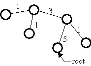
It’s usually much cheaper to broadcast the same information to n places than to send it individually to each of the n places. This is especially true when the physical communication medium is a broadcast medium. An extreme example is direct digital satellite broadcast, which can send a megabyte to everyone in the US for about $.05; compare this with about $.02 to send a megabyte to one place on a local ISDN telephone link. But even when the physical medium is point to point and switches are needed to connect n places, as is the case with telephony or ATM, it’s still much cheaper to broadcast because the switches can be configured in a tree rooted at the source of the broadcast and the message needs to traverse each link only once, instead of once for each node that the link separates from the root. Figure 3 shows the number of times a message from the root would traverse each link if it were sent individually to each node; in a broadcast it traverses each link just once.
|
Fig. 3: The cost of doing broadcast with point-to-point communication |
Historically, most LANs have done broadcast automatically, in the sense that every message reaches every node on the LAN, even if the underlying electrons or photons don’t have this property; we will study broadcast networks in more detail later on. Switched LANs are increasingly popular, however, because they can dramatically increase the total bandwidth without changing the bandwidth of a single link, and they don’t do broadcast automatically. Instead, the switches must organize themselves into a spanning tree that can deliver a message originating anywhere to every node.
Broadcast is a special case of ‘multicast’, where messages go to a subset of the nodes. As nodes enter and leave a multicast group, the shape of the tree that spans all the nodes may change. Note that once the tree is constructed, any node can be the root and send to all the others. There are clever algorithms for constructing and maintaining this tree that are fairly widely implemented in the Internet.[6]
Real time
Although often ignored, real time plays an important role in distributed systems. It is used in three ways:
To decide when to retry a transmission if there is no response. This often happens when there is some kind of failure, for instance a lost Internet IP packet, as part of an end-to-end protocol. If the retransmission timeout is wrong, performance will suffer but the system will usually still work. When timeouts are used to control congestion, however, making them too short can cause the bandwidth to drop to 0.
To ensure the stability of a load control system based on feedback. This requires knowing the round trip time for a control signal to propagate. For instance, if a network provides a ‘stop’ signal when it can’t absorb more data, it should have enough buffering to absorb the additional data that may be sent while the ‘stop’ signal makes its way back to the sender. If the ‘stop’ comes from the receiver then the receiver should have enough buffering to cover a sender-receiver-sender round trip. If the assumed round-trip time is too short, data will be lost; if it’s too long, bandwidth will suffer.
To implement “bounded waiting” locks, which can be released by another party after a timeout. Such locks are called ‘leases’; they work by requiring the holder of the lock to either fail or release it before anyone else times out.[7]. If the lease timeout is too short the system won’t work. This means that all the processes must have clocks that run at roughly the same rate. Furthermore, to make use of a lease to protect some operation such as a read or write, a process needs an upper bound on how the operation can last, so that it can check that it will hold the lease until the end of that time. Leases are used in many real systems, for example, to control ownership of a dual-ported disk between two processors, and to provide coherent file caching in distributed file systems. See handout 18 on consensus for more about leases.
Fault tolerance
Fault tolerance is always based on redundancy. The simplest strategy for fault-tolerance is to get the redundancy by replicating fairly large components or actions. Here are three ways to do it:
1. Duplicate components, detect errors, and ignore bad components (replicate in space).
2. Detect errors and retry (replicate in time, hoping the error is transient).
3. Checkpoint,
detect errors, crash, reconfigure without the bad components, and
restart from the
checkpoint (a more general way to replicate in time)
There is a space-time tradeoff illustrated in the following picture.[8]
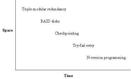
Highly available systems use the first strategy. Others use the second and third, which are cheaper as long as errors are not too frequent, since they substitute duplication in time for duplication in space (or equipment). The second strategy works very well for communications, since there is no permanent state to restore, retry is just resend, and many errors are transient. The third strategy is difficult to program correctly without transactions, which are therefore an essential ingredient for complex fault tolerant systems.
Another way to look at the third approach is as failover to an alternate component and retry; this requires a failover mechanism, which for communications takes the simple form of changes in the routing database. An often-overlooked point is that unless the alternate component is only used as a spare, it carries more load after the failure than it did before, and hence the performance of the system will decrease.
In general, fault tolerance requires timeouts, since otherwise you wait indefinitely for a response from a faulty component. Timeouts in turn require knowledge of how long things should take, as we saw in the previous discussion of real time. When this knowledge is precise, we call the system ‘synchronous’; timeouts can be short and failure detection rapid, conditions that are usually met at low levels in a system. It’s common to design a snoopy cache, for instance, on the assumption that every processor will respond in the same cycle so that the responses can be combined with an ‘or’ gate.[9] Higher up there is a need for compatibility with several implementations, and each lower level with caching adds uncertainty to the timing. It becomes more difficult to set timeouts appropriately; often this is the biggest problem in building a fault-tolerant system. Perhaps we should specify the real-time performance of systems more carefully, and give up the use of caches such as virtual memory that can cause large variations in response time.
All these methods have been used at every level from processor chips to distributed systems. In general, however, below the level of the LAN most systems are synchronous and not very fault-tolerant: any permanent failure causes a crash and restart. Above that level most systems make few assumptions about timing and are designed to keep working in spite of several failures. From this difference in requirements follow many differences in design.
In a system that cannot be completely reset, it is important to have self-stabilization: the system can get from an arbitrary state (which it might land in because of a failure) to a good state.[10]
In any fault-tolerant system the algorithms must be ‘wait-free’ or ‘non-blocking’, which means that the failure of one process (or of certain sets of processes, if the system is supposed to tolerate multiple failures) cannot keep the system from making progress.[11] Unfortunately, simple locking is not wait-free. Locking with leases is wait-free, however. We will study some other wait-free algorithms that don’t depend on real time. We said a little about this subject in handout 14 on practical concurrency.[12]
Performance of communication
Communication has the same basic performance measures as anything else: latency and bandwidth.
· Latency: how long a minimum communication takes. We can measure the latency in bytes by multiplying the latency time by the bandwidth; this gives the capacity penalty for each separate operation. There are standard methods for minimizing the effects of latency:
Caching reduces latency when the cache hits.
Prefetching hides latency by the distance between the prefetch and the use.
Concurrency tolerates latency by giving something else to do while waiting.
· Bandwidth: how communication time grows with data size. Usually this is quoted for a two-party link. The “bisection bandwidth” is the minimum bandwidth across a set of links that partition the system if they are removed; it is a lower bound on the possible total rate of uniform communication. There are standard methods for minimizing the cost of bandwidth:
Caching saves bandwidth when the cache hits.
More generally, locality saves bandwidth when cost increases with distance.
‘Combining networks’ save bandwidth to a hot spot by combining several operations into one, several loads or increments for example.
Code shipping saves bandwidth by sending the code to the data.[13]
In addition, there are some other issues that are especially important for communication:
· Connectivity: how many parties you can talk to. Sometimes this is a function of latency, as in the telephone system, which allows you to talk to millions of parties but only one at a time.
· Predictability: how much latency and bandwidth vary with time. Variation in latency is called ‘jitter’; variation in bandwidth is called ‘burstiness’. The biggest difference between the computing and telecommunications cultures is that computer communication is basically unpredictable, while telecommunications service is traditionally highly predictable.
· Availability: the probability that an attempt to communicate will succeed.
Uniformity of performance at an interface is often as important as absolute performance, because dealing with non-uniformity complicates programming. Thus performance that depends on locality is troublesome, though often rewarding. Performance that depends on congestion is even worse, since congestion is usually much more difficult to predict than locality. By contrast, the Monarch multiprocessor[14] provides uniform, albeit slow, access to a shared memory from 64K processors, with a total bandwidth of 256 Gbytes/sec and a very simple programming model. Since all the processors make memory references synchronously, it can use a combining network to eliminate many hot spots.
Specifications for communication
Regardless of the type of message being transported, all the communication systems we will study implement one of a few specifications. All of them are based on the idea of sending and receiving messages through a channel. The channel has state that is derived from the messages that have been sent. Ideally the state is the sequence of messages that have been sent and not yet delivered, but for weaker specifications the state is different. In addition, a message may be acknowledged. This is interesting if the spec allows messages to be lost, because the sender needs to know whether to retransmit. It may also be interesting if the spec does not guarantee prompt delivery and the sender needs to know that the message has been delivered.
None of the specs allows for messages to be corrupted in transit. This is because it’s easy to convert a corrupted message into a lost message, by attaching a sufficiently good checksum to each message, and discarding any message with an incorrect checksum. It’s important to realize that the definition of a ‘sufficiently good’ checksum depends on a model of what kind of errors can occur. To take an extreme example, if the errors are caused by a malicious adversary, then the checksum must involve some kind of secret, called a ‘key’; such a checksum is called a ‘message authentication code’. At the opposite extreme, if only single-bit errors are expected, (which is likely to be the case on a fiber optic link where the errors are caused by thermal noise) then a 32-bit CRC may be good; it is cheap to compute and it can detect three or fewer single-bit errors in a message of less than about 10 KB. In the middle is an unkeyed one-way function like MD5.[15]
These specs are for messages between a single sender and a single receiver. We allow for lots of sender-receiver pairs initially, and then suppress this detail in the interests of simplicity.
MODULE Channel[
M, % Message
A ] = % Address
TYPE Q = SEQ M % Queue: channel state
SR = [s: A, r: A] % Sender - Receiver
K = ENUM[ok, lost] % acK
...
END Channel
Perfect channels
A perfect channel is just a FIFO queue. This one is unbounded. Note that Get blocks if the queue is empty.
VAR q := (SR -> Q){* -> {}} % all initially empty
APROC Put(sr, m) = << q(sr) := q(sr) + {m} >>
APROC Get(sr) -> M = << VAR m | m = q(sr).head => q(sr) := q(sr).tail; RET m >>
Henceforth we suppress the sr argument and deal with only one channel, to reduce clutter in the specs.
Reliable channels
A reliable channel is like a perfect channel, but it can be down, in which case the channel is allowed to lose messages. Now it’s interesting to have an acknowledgment. This spec gives the simplest kind of acknowledgment, for the last message transmitted. Note that GetAck blocks if status is nil; normally this is true iff q is non-empty. Also note that if the channel is down, status can become lost even when no message is lost.
VAR q := {}
status : (K + Null) := ok
down := false
APROC Put(m) = << q := q + {m},
status := nil >>
APROC Get() -> M = << VAR m | m = q.head =>
q := q.tail; IF q = {} => status := ok [*]
SKIP FI; RET m >>
APROC GetAck() -> K = << VAR k | k =
status => status := ok; RET k >>
APROC Crash() = down := true
APROC Recover() = down := false
THREAD Lose() = DO % internal action
<< down =>
IF
VAR q1, q2, m | q = q1 + {m} + q2 =>
q := q1 + q2; IF q2 = {} => status := lost
[*] SKIP FI
[*] status := lost
FI >>
[*] SKIP OD
Unreliable channels
An unreliable channel is allowed to lose, duplicate, or reorder messages at any time. This is an interesting spec because it makes the minimum assumptions about the channel. Hence anything built on this spec can work on the widest variety of channels. The reason that duplication is important is that the way to recover from lost packets is to retransmit them, and this can lead to duplication unless a lot of care is taken, as we shall see in handout 25. A variation (not given here) bounds the number of times a message can be duplicated.
VAR q := Q{} % as a multiset!
APROC Put(m) = << q := q + {m} >>
APROC Get() -> M =
<< VAR m | m IN q => q := q - {m}; RET m >>
THREAD
Lose() = DO VAR
m | << m IN q => q := q - {m} >> [*] SKIP OD
THREAD Dup() = DO VAR m | << m IN q => q := q + {m} >> [*] SKIP OD
An unreliable FIFO channel is a model of a point-to-point wire or of a broadcast LAN without bridging or switching. It preserves order and does not duplicate, but can lose messages at any time. This channel has Put and Get exactly like the ones from a perfect channel, and a Lose much like the unreliable channel’s Lose.
VAR q := Q{} % all initially empty
APROC
Put(m) =
<< q := q + {m} >>
APROC Get() -> M = << VAR m | m =
q.head => q := q.tail; RET m >>
THREAD Lose() =
DO << VAR q1, q2, m | q = q1 + {m} + q2 => q := q1 + q2 >> [*] SKIP OD
These specs can also be written in an ‘early-decision’ style that decides everything about duplication and loss in the Put. As usual, the early decision spec is shorter. It takes a prophecy variable (handout 8) to show that the code with Lose and Dup implements the early decision spec for the unreliable FIFO channel, and for the unordered channel it isn’t true, because the early decision spec cannot deliver an unbounded number of copies of m. Prophecy variables can work for infinite traces, but there are complicated technical details that are beyond the scope of this course.
Here is the early decision spec for the unreliable channel:
VAR q := Q{} % as a multiset!
APROC Put(m) = << VAR i: Nat => q := q + {j
:IN i.seq | | m} >>
APROC Get() -> M =
<< VAR m | m IN q => q := q - {m}; RET m >>
and here is the one for the unreliable channel
VAR q := Q{} % all initially empty
APROC
Put(m) =
<< q := q + {m} [] SKIP >>
APROC Get() -> M = << VAR m | m =
q.head => q := q.tail; RET m >>
.