A serious problem in microchip design is the distribution of clock
signals. There are many latches scattered about the chip which must
recieve a clock signal simultaneously, and one clock generator which
generates the signal. Simply stringing a wire between this source and
all of the latches is not feasable, since there are limits on how much
capacitance can be on a single wire before any signals on that wire
are degraded due to noise, and the capacitance is proportional to the
amount of wire present. Therefore, a number of repeaters must be
inserted to copy the clock signal and break up the single large net
into a number of smaller ones, each connecting a smaller set of
latches. These nets are still possibly too large, so this process
must be repeated a number of times, forming a tree structure which
will allow the clock signal to remain strong enough to be noise-free
as it travels from the signal generator to the latches.
Unfortunately, the signal must arrive simultaneously at all of the
latches, and the propigation time of a signal across a net is
determined by the size of the net. Thus, all branches of the tree
must be balanced, otherwise some latches will recieve the signal too
early or too late relative to their neighbors.
In addition, this tree structure will contain an immense amount of
wire and a large number of repeaters. This will cause unacceptably
large power consumption unless the tree is made as small as possible,
subject to the balance constraint, and a number of other constraints
on individual nets within the tree which guarantee signal integrity.
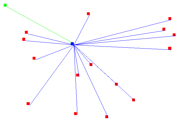
The following picture illustrates a miniature version of this problem.
The green dot is the clock source, and the red dots are the latches
that need to recieve the clock signal. The signal travels from the
source through a net (green line) to the first level repeater (blue
square) to a second level net (blue line) to the latches. In
practice, a tree would have far more latches (tens of thousands), and
would therefore be several levels deep to satisfy the size constraints on all levels. This tree needs to be optimized,
because the single blue net is too large; it goes to a large number of
destinations, and they are widely scattered so it requires a lot of
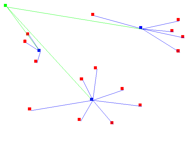
wire, both of which are problems.  In the initial optimization, the blue net is broken up into a number
of small nets, each of which is driven by a different repeater. These
nets are all sufficiently small that the clock signal will not
degrade, so this is now a legal clock tree. Unfortunately, to be optimal, the tree
must be balanced as well. The leftmost net is significantly smaller,
both in number of latches and in amount of wire, than the other two
nets. If left this way, in a post-optimization step that net would be
made larger, by having the wire take an indirect route to its
destination, and/or by adding extra do-nothing sinks to the net to
make it the same size as the other two, so that the clock signal would
take the same amount of time to traverse each branch of the tree.
Unfortunately, chip designers want to make the clock tree be as small
as possible, to minimize power consumption, so adding extra useless
elements will make the tree sub-optimal.
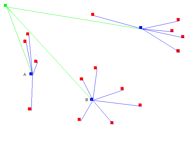
  Thus, the nets are then passed into the refinement optimizer. Pairs
of nets are chosen, and latches are swapped between them in an attempt
to make them balanced, and as small as possible (if two nets both get
smaller, at worst you will have a post-processing step that makes them
both larger again, but at best one of them will later be optimized
with the largest net in the set, causing it to get smaller, thus
bringing down the cost of all of the nets in the set). In this
example, net A, which was the smallest one, was compared with net B,
which was the largest one. Swapping one of the pins from B to A made
A larger than it had been before, and brought it closer in size to B,
improving the score (they are now closer to balanced).
 In practice, this must be done repeatedly, since sometimes changes
must propigate a lot; if nets on one side of the chip are larger than
those on the other side, it may take several iterations for the
gradient to flatten out. Optimization is done at the leaf level of
the tree, and then works up the tree using the same methods.
Back to top page
 In the initial optimization, the blue net is broken up into a number
of small nets, each of which is driven by a different repeater. These
nets are all sufficiently small that the clock signal will not
degrade, so this is now a legal clock tree. Unfortunately, to be optimal, the tree
must be balanced as well. The leftmost net is significantly smaller,
both in number of latches and in amount of wire, than the other two
nets. If left this way, in a post-optimization step that net would be
made larger, by having the wire take an indirect route to its
destination, and/or by adding extra do-nothing sinks to the net to
make it the same size as the other two, so that the clock signal would
take the same amount of time to traverse each branch of the tree.
Unfortunately, chip designers want to make the clock tree be as small
as possible, to minimize power consumption, so adding extra useless
elements will make the tree sub-optimal.
  Thus, the nets are then passed into the refinement optimizer. Pairs
of nets are chosen, and latches are swapped between them in an attempt
to make them balanced, and as small as possible (if two nets both get
smaller, at worst you will have a post-processing step that makes them
both larger again, but at best one of them will later be optimized
with the largest net in the set, causing it to get smaller, thus
bringing down the cost of all of the nets in the set). In this
example, net A, which was the smallest one, was compared with net B,
which was the largest one. Swapping one of the pins from B to A made
A larger than it had been before, and brought it closer in size to B,
improving the score (they are now closer to balanced).
 In practice, this must be done repeatedly, since sometimes changes
must propigate a lot; if nets on one side of the chip are larger than
those on the other side, it may take several iterations for the
gradient to flatten out. Optimization is done at the leaf level of
the tree, and then works up the tree using the same methods.
Back to top page