|
To print these notes, use the PDF version. |
|
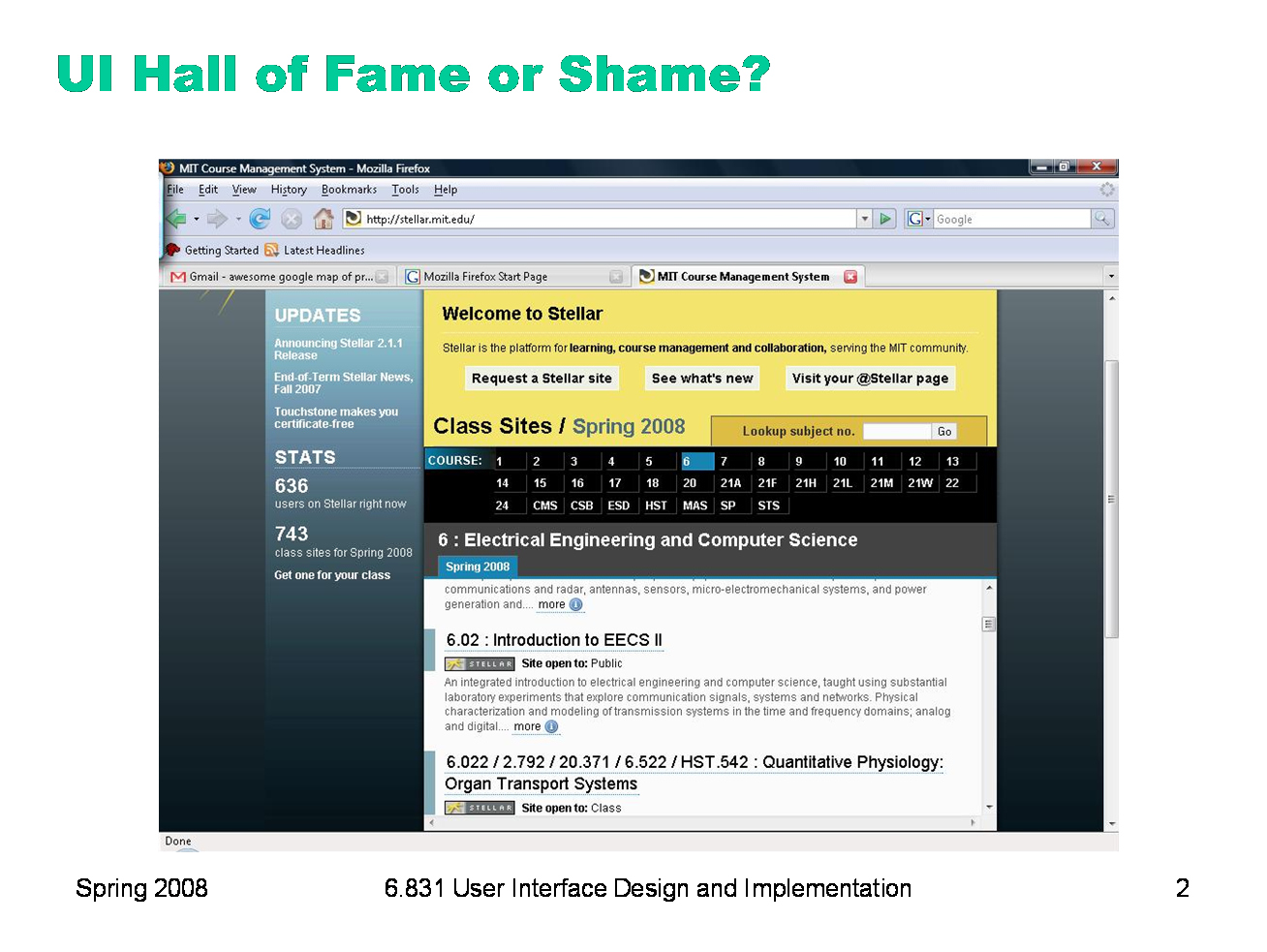
From Lydia Chilton: “Stellar is MIT's internal course website service. Uses want to navigate the Stellar homepage to find their class' Stellar page. Each course has a list of about 100 classes. Unfortunately for the user, the scroll panel only displays two classes at a time.” (Also mentioned by Stanley Wang)
Let’s discuss the front page of Stellar with respect to any of the UI design principles we’ve talked about, e.g.: - learnability - visibility - user control & freedom - errors - efficiency - graphic design - color design
|
|
Today’s lecture is about advanced output techniques. Most of what we’ll talk about is coordinate transforms, which change the coordinate system in which (x,y) coordinates are interpreted. But we’ll also touch on clipping and a few other useful tricks for output, like changing the drawing context that you pass down to your children in order to modify their appearance.
|
|
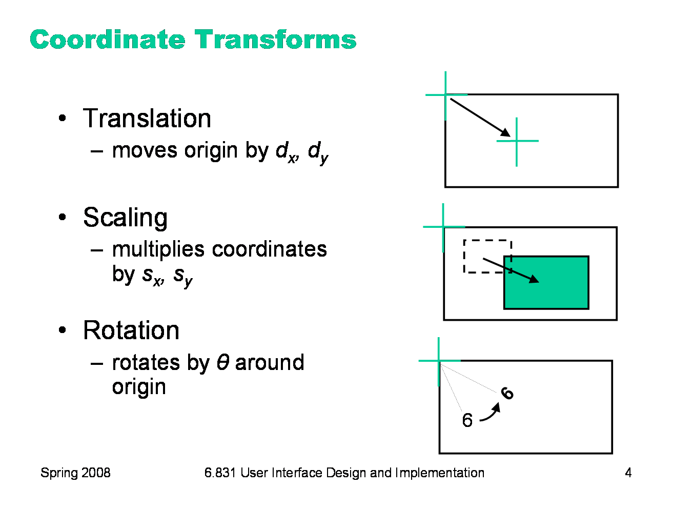
Coordinate systems are relevant to all output models. In the component model, every component in a view hierarchy has its own local coordinate system, whose origin is generally at the top left corner of the component, with the y axis increasing down the screen. (Postscript is an exception to this rule; its origin is the bottom left, like conventional Cartesian coordinates.) When you’re drawing a component, you start with the component’s local coordinate system. But you can change this coordinate system (a property of the graphics context) using three transformations: Translation moves the origin, effectively adding (dx,dy) to every coordinate used in subsequent drawing. Scaling shrinks or stretches the axes, effectively multiplying subsequent x coordinates by a scaling factor sx and subsequent y coordinates by sy. Rotation rotates the coordinate system around the origin.
|
|
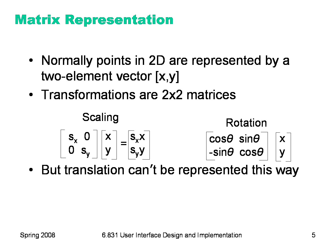
These operations are typically represented internally by a transform matrix which can be multiplied by a coordinate vector [x,y] to map it back to the original coordinate system. Scaling and rotation are easy to represent by matrix multiplication, but translation seems harder, since it involves vector addition, not multiplication.
|
|
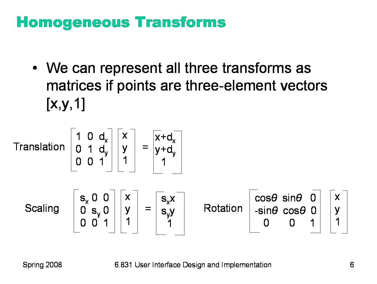
Homogeneous transforms offer a way around this problem, allowing translations to be represented homogeneously with the other transforms, so that the effect of a sequence of coordinate transforms can be multiplied together into a single matrix. Homogeneous transforms add a dummy element 1 to each coordinate vector.
|
|
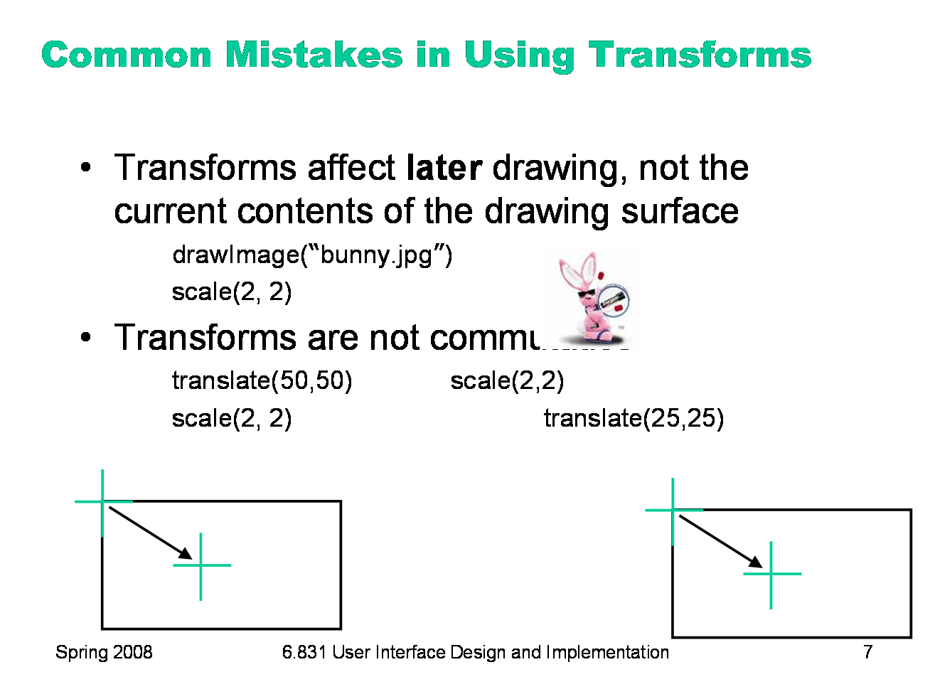
One misconception in using transforms is that they apply to what you’ve already put on the drawing surface — as if you were doing a rotate, scale, or move operation in a drawing program. That’s not the way it works. Transforms change the coordinate system for subsequent drawing calls. In the example shown here, the bunny already drawn won’t be affected by the later scale() call. Another misconception is that you can freely reorder transforms — e.g., that you can gather up all the translates, scales, and rotates you’ll have to do, and do them in a single place at the beginning of your paint() method. In general, that doesn’t work, because transform operations are not commutative. Transforms of the same type are commutative, of course — two translates can be done in either order, and in fact can trivially be combined into a single translate by adding their components. Likewise, two scaling operations can be commuted (and combined by multiplying), and two rotations can be commuted (or combined by adding the angles). But two operations of different types cannot be done in any order, because the results change depending on the order.
|
|
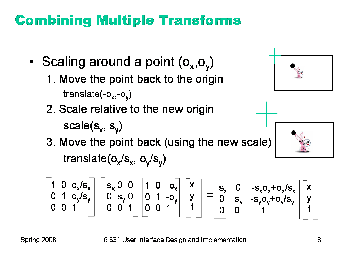
Rotation around a point is similar: first make the point the origin, then rotate, and then move the point back. Undoing the translate is harder, however, so Swing simplifies things by actually giving you a rotate(theta,x,y) method that does all the work.
|
|
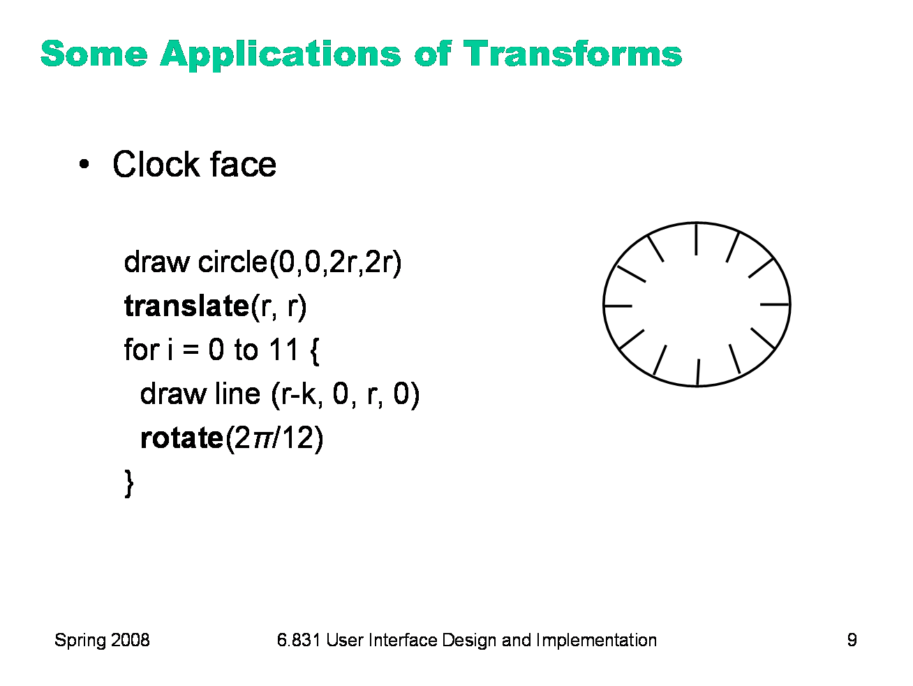
Transforms can make a lot of drawing easier. For example, if you have to draw the same thing at several places, just write one function that draws the thing at (0,0), and use translate() before each call to the function to put (0,0) in the right place. Here’s a similar example — rather than calculate where the ticks of a clock face should go, just use rotation around the center of the clock face so that you can draw the same tick each time. The radius of the clock face is r, and the length of each clock tick line is k.
|
|
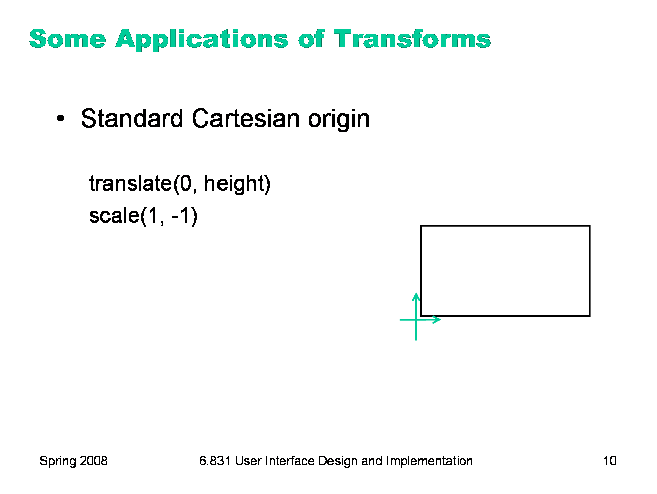
Another simple thing that’s sometimes useful is transforming to the more familiar Cartesian coordinate system, in which the origin is the lower-left corner. Why do we have to scale() as well as translate()?
|
|
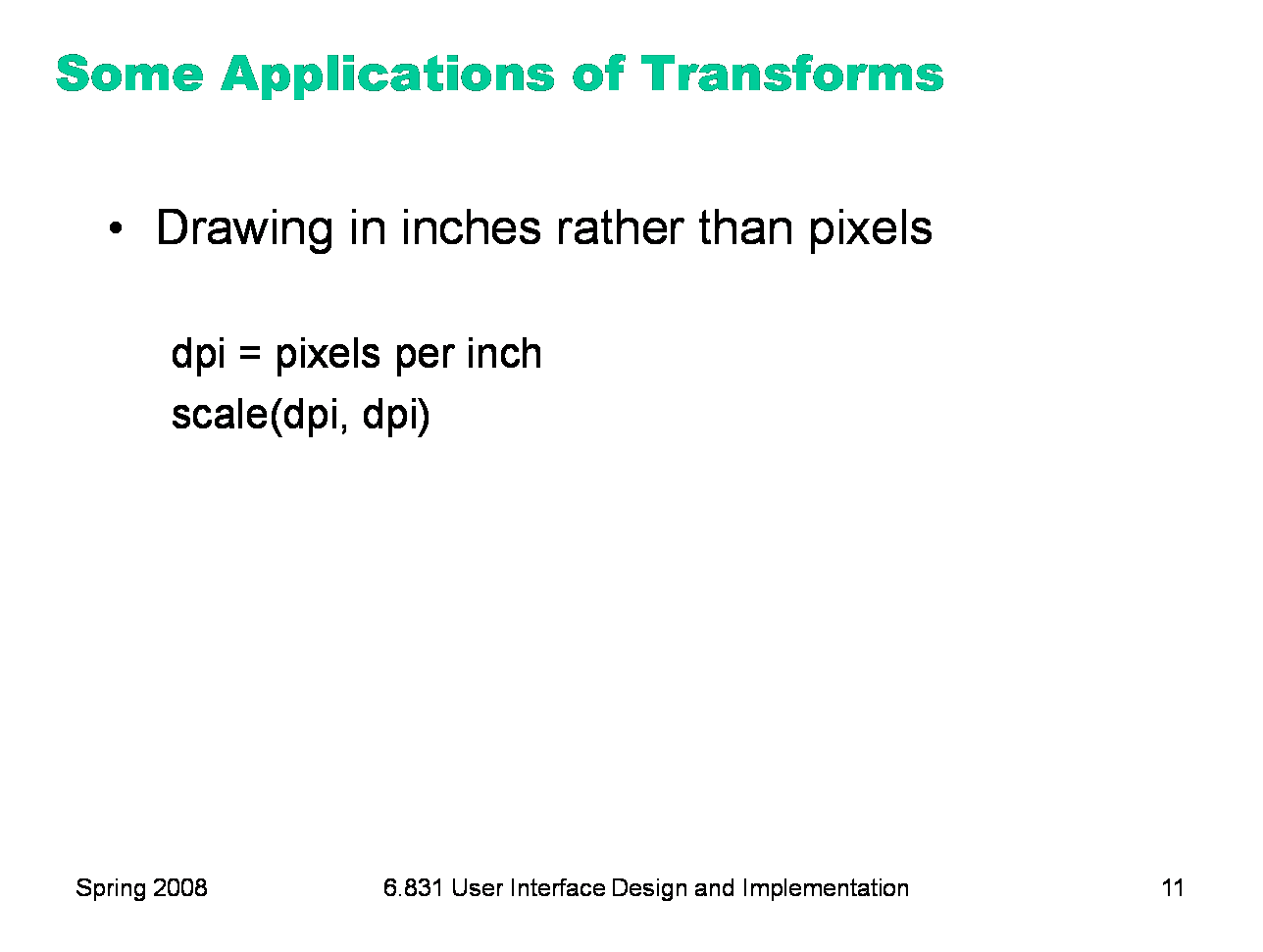
One more simple example: if you want to draw in physical units, some toolkits enable you to find out what the (approximate) resolution of the screen is, in pixels per inch, and you can set your scale to that, so that you can draw a line by giving its coordinates in inches rather than pixels.
|
|
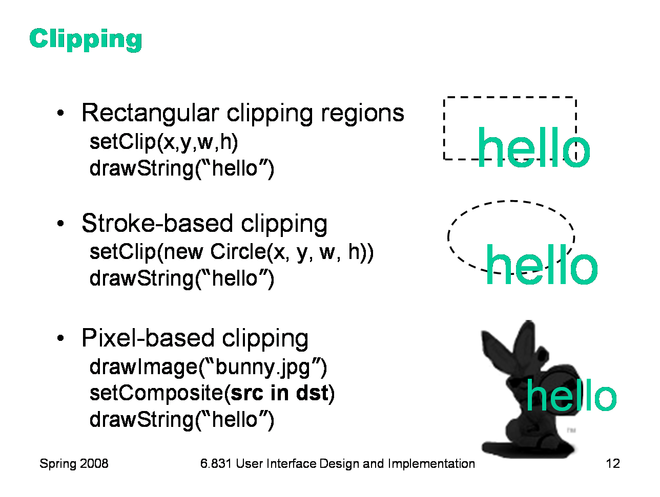
Virtually every GUI toolkit supports rectangular clipping regions, because it’s an essential part of the view hierarchy pattern — parents clip their children by default. Clipping is also used for damage regions, as we saw in the previous Output lecture. The clipping region is also under your control, if you want it to be — most graphics contexts allow you to set your own clipping region that will filter your subsequent drawing calls. Often, however, the clipping region that you set does not override the clipping region set by your parent or set by the damage region — instead, the final clipping region used for drawing may be the intersection of the region you provide and the damage region. One nice feature of rectangles is that the intersection of any number of rectangles is always a rectangle (or the empty set), so the drawing package doesn’t have to worry about more complicated shapes. Good drawing systems (like Java Swing, Postscript/PDF, and Apple Quartz) let you do nonrectangular clipping, which comes in two flavors. Stroke-based clipping uses an abstract shape for clipping, which might be simple (like a circle) or complex. In Swing, you can build up a complex shape by taking unions and intersections of simple shapes, or by defining its boundary using line segments and curves. The other approach uses the pixel model and alpha compositing. The clipping region is an image, which is composited with a drawing using the in compositing operator we saw earlier in this lecture.
|
|
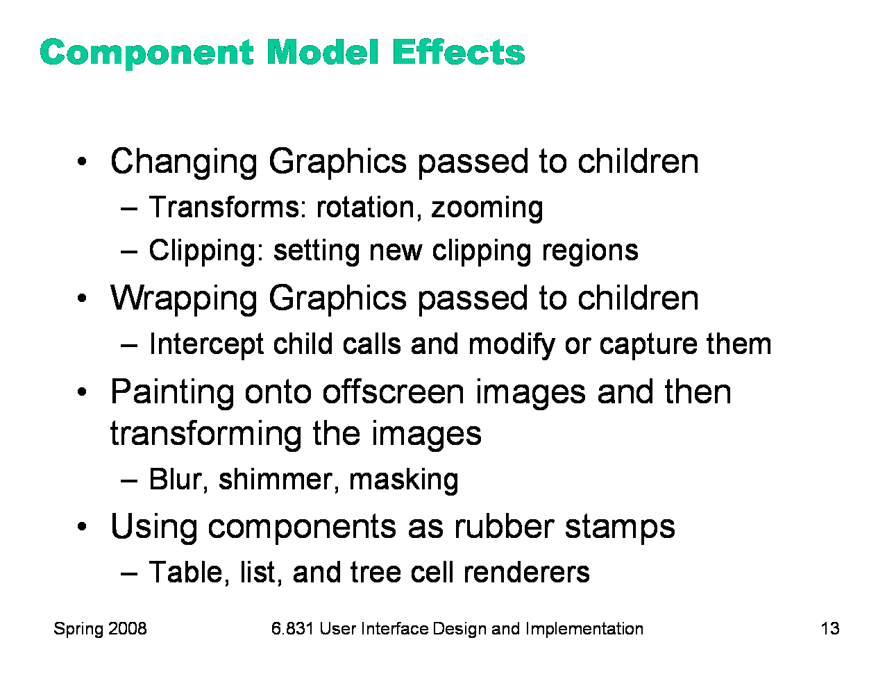
Using visual effects in the component model has some special problems, especially if you want your container to be decoupled from its component children — i.e., if you want it to handle arbitrary children who might draw themselves in arbitrary ways. Here are some tricks you can use to change the way your children draw themselves. (Some of these ideas come from a good paper: Edwards et al, “Systematic Output Modification in a 2D User Interface Toolkit”, UIST ’97.) One technique is to change the defaults in the graphics context you pass down to your children. For example, you can apply transformations to the graphics context to persuade your children to draw in different places, or magnify or shrink their results. One problem with these kinds of transformations is that they can screw up input and automatic redraw. If a component is drawn transformed, you have to transform hit testing and input event coordinates in the same way; similarly, if the component asks to repaint itself, its repaint rectangle has to be transformed likewise. So if your toolkit doesn’t support transforming input and redraw, you should restrict the use of this technique to components that don’t expect input and that will notify you if they change. Another trick is to put a wrapper around the Graphics object — a wrapper that delegates to the inner Graphics object, but changes the way certain kinds of drawing is done. For example, you could write a Graphics wrapper that produces a drop shadow underneath every stroke drawn by a child. You can also create an offscreen image buffer, create a graphics context that uses it as a drawing surface, and then have your children paint themselves through this new graphics context. This gives you complete access to the pixel image produced by your children, so you can apply arbitrary effects to it. For example, you can create a drop shadow from the entire image, using masking; you can apply a Gaussian filter to it to blur the sharp edges; you can animate a shimmering effect. The result of these operations then gets copied to the onscreen drawing surface. The final component-model technique is concerned not with components as children, but rather components as encapsulated drawing procedures — rubber stamps that, given some parameters, can paint a rendering of those parameters. For example, you can create a label widget, fill in its text, font, x, y, and size, and call its paint() method to paint it on an arbitrary graphics context, even though you never added it to a view hierarchy. Several Swing classes use this approach — JList, JTable, and JTree for example. These classes can be configured with renderers which are simply component factories, but the components are used only for stamping out output. This approach is even lighter-weight than the glyph pattern. You might need only one JLabel to stamp out all the text in a column, for example.
|
|
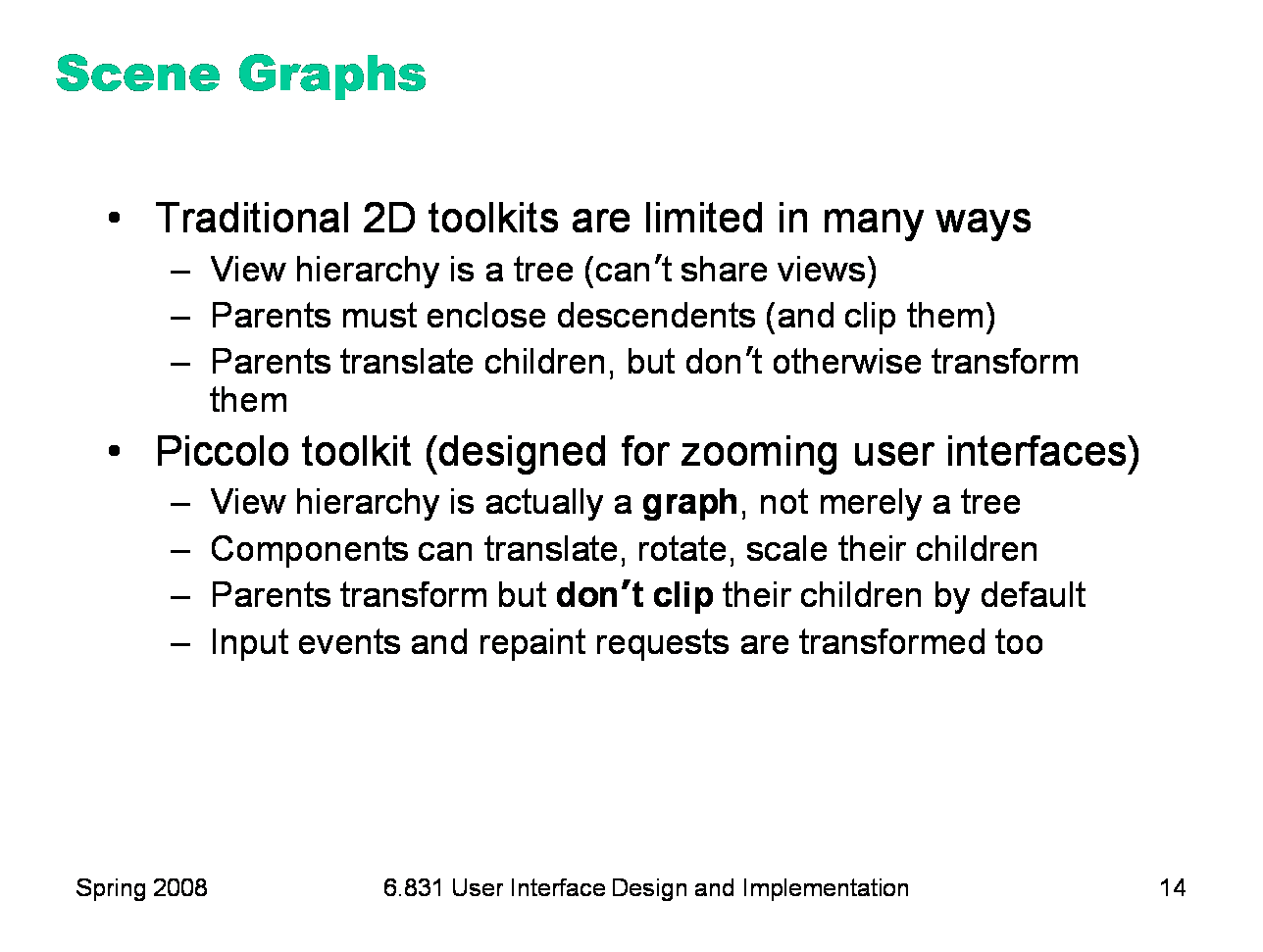
Finally, let’s look at Piccolo, a novel UI toolkit developed at University of Maryland. Piccolo is specially designed for building zoomable interfaces, which use smooth animated panning and zooming around a large space. Piccolo has a view hierarchy consisting of PNode objects. But the hierarchy is not merely a tree, but in fact a graph: you can install camera objects in the hierarchy which act as viewports to other parts of the hierarchy, so a component may be seen in more than one place on the screen. Another distinction between Piccolo and other toolkits is that every component has an arbitrary transform relative to its parent’s coordinate system — not just translation (which all toolkits provide), but also rotation and scaling. The toolkit automatically handles transforming not only output, but also input event coordinates, hit tests, and repaint requests. Furthermore, in Piccolo, parents do not clip their children by default. If you want this behavior, you have to request it by inserting a special clipping object (a component) into the hierarchy. As a result, components in Piccolo have two bounding boxes — the bounding box of the node itself (getBounds()), and the bounding box of the node’s entire subtree (getFullBounds()). The widget set for Piccolo is fairly small by comparison with toolkits like Swing and .NET, probably because Piccolo is a research project with limited resources. It’s worth noting, however, that Piccolo provides reusable components for shapes (e.g. lines, rectangles, ellipses, etc), which in other toolkits would require revering to the stroke model. Piccolo home page: http://www.cs.umd.edu/hcil/piccolo/ Overview: http://www.cs.umd.edu/hcil/piccolo/learn/patterns.shtml API documentation: http://www.cs.umd.edu/hcil/jazz/learn/piccolo/doc-1.1/api/ |
|
|